Animatronic Project

Building a robot head

Project Info

I began learning 3D CAD in November of 2017 to design an Animatronic robot head as an exercise in engineering and because I've always been fascinated by the special creature effects used in sci-fi movies I grew up with. So I wanted to create a 3D printed animatronic character that could be puppeteered using servo motors and RC radio commands.

Work Required

The challenge was to create mechanical parts that would rotate a pair of eye balls, blink the eye lids, open and close the jaw and tilt the head on three axis. Having no prior experience I started looking through online images and videos to understand the mechanics used in robotics and animatronic characters.

3D Printed Animatronic

project

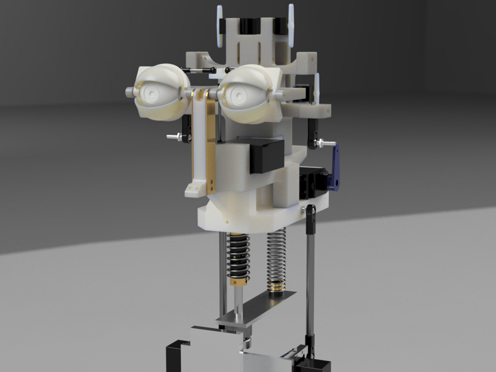
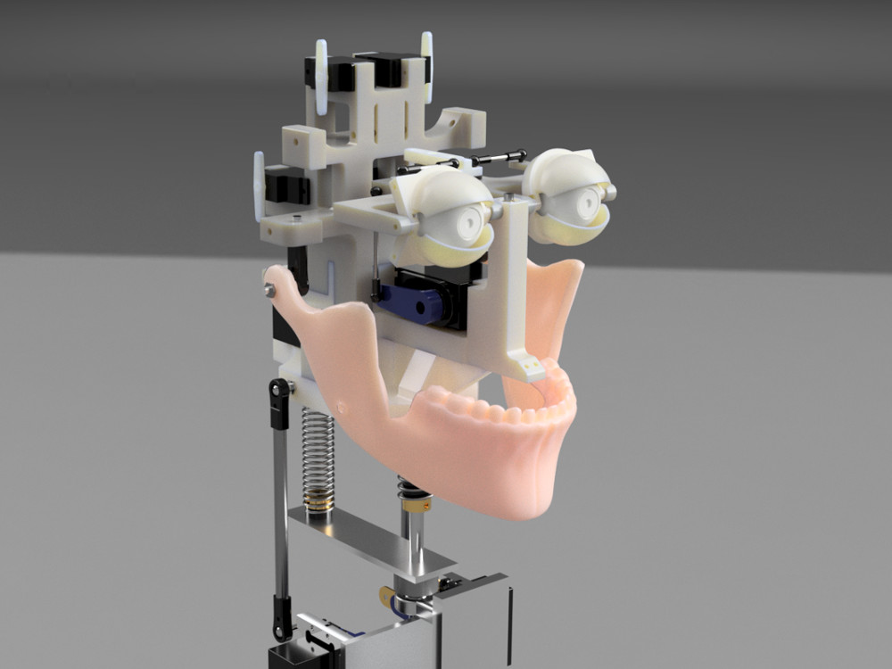
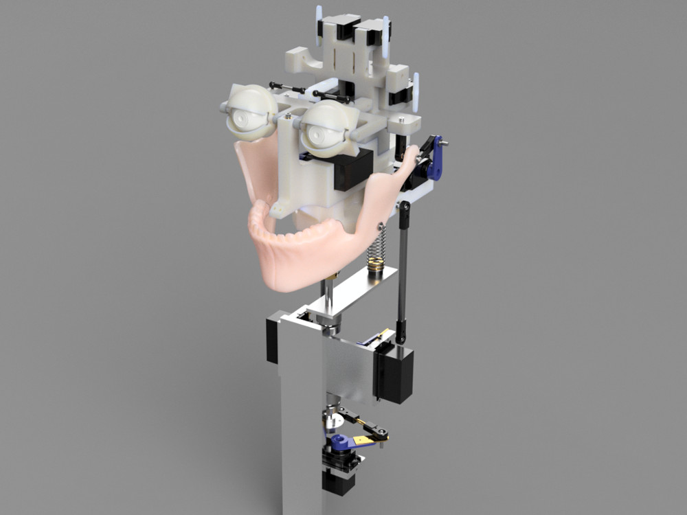
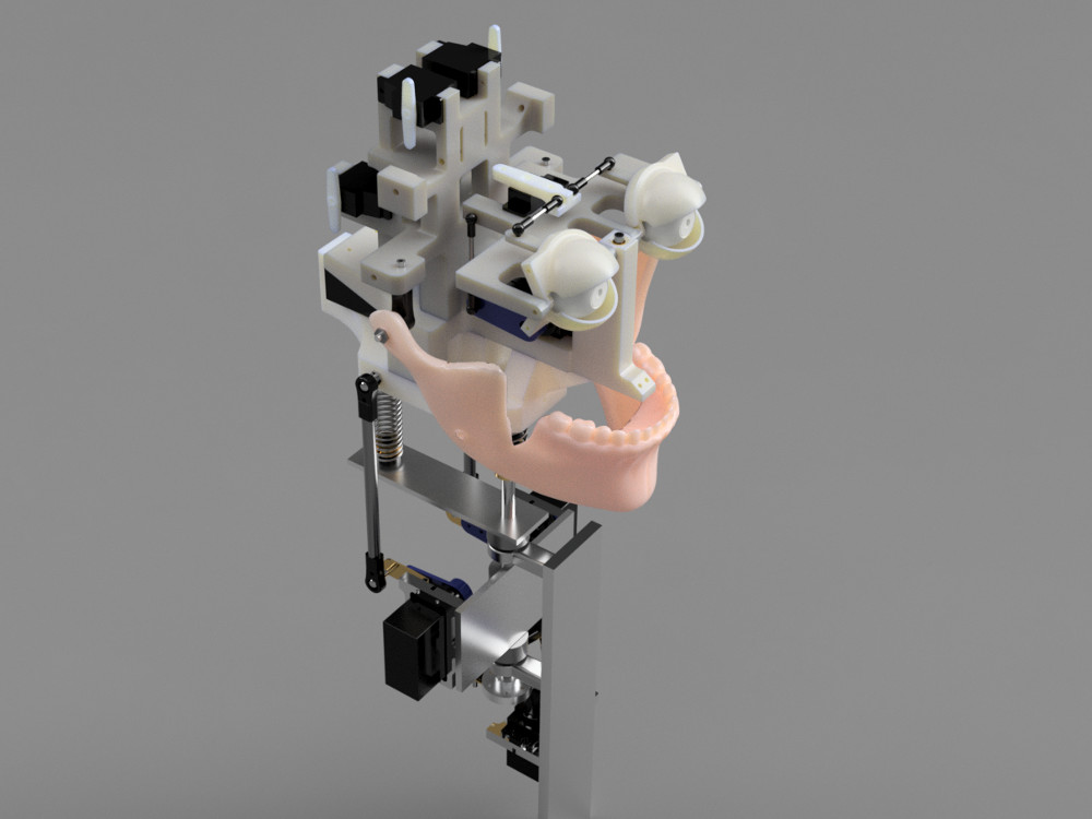
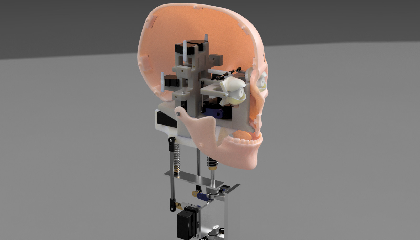
Designing everything from scratch

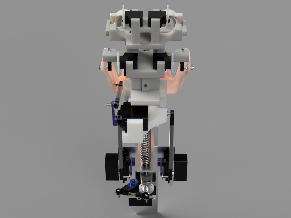
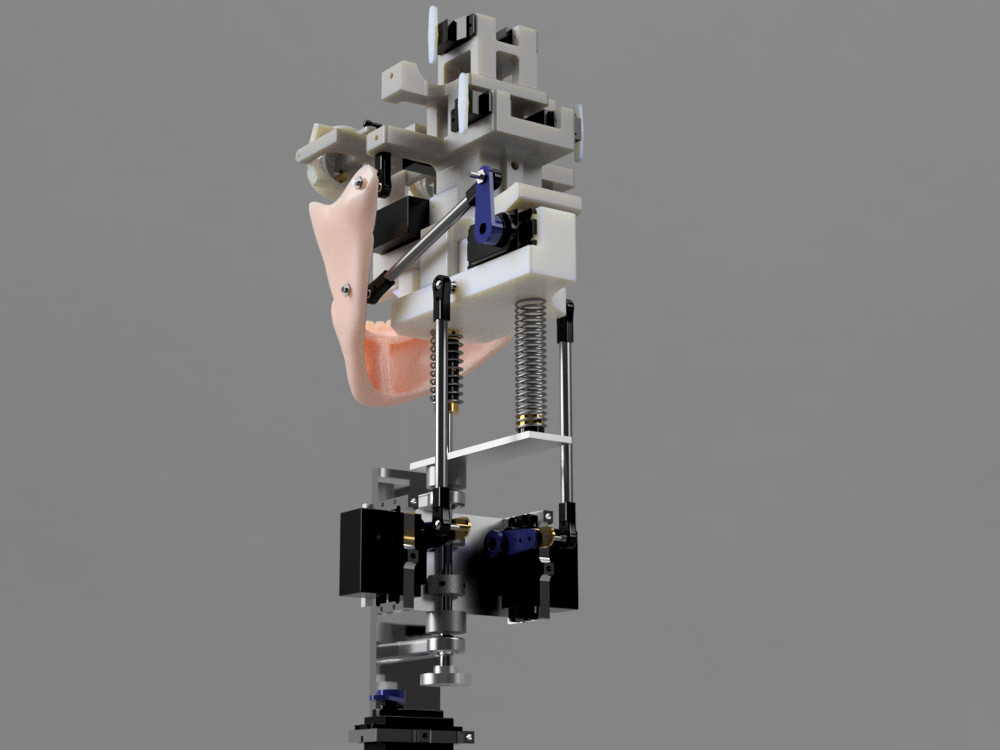
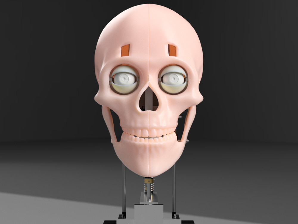
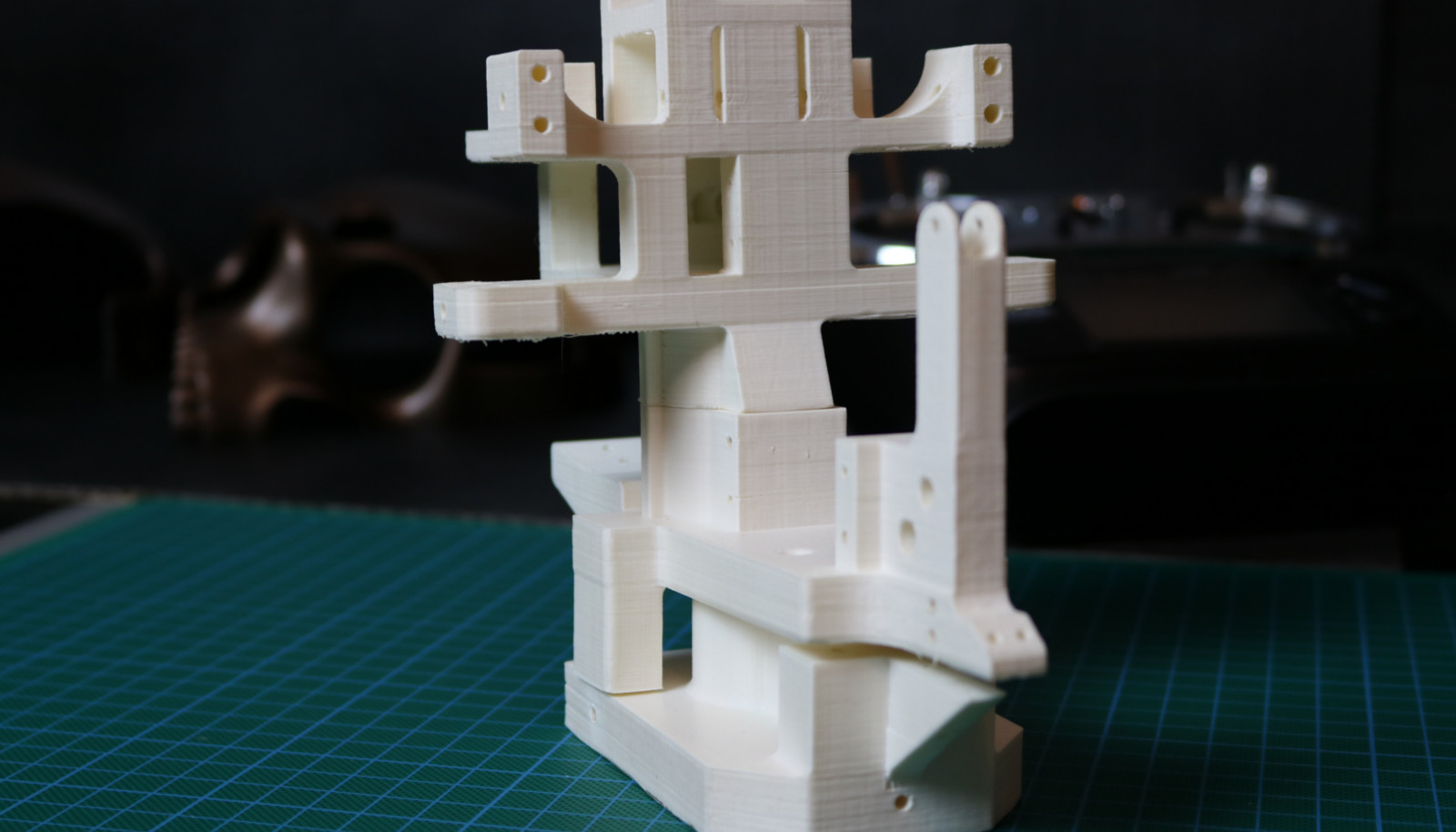
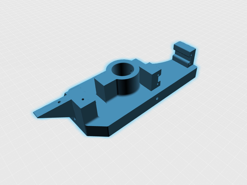
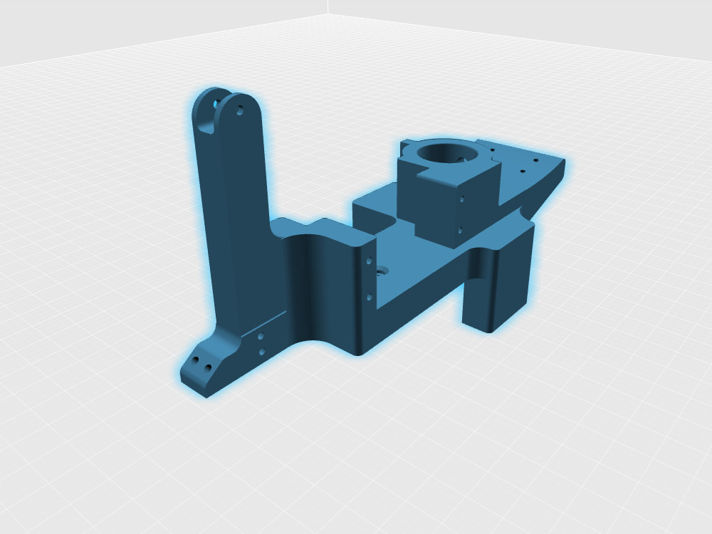
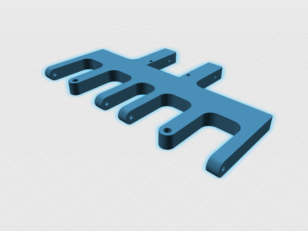
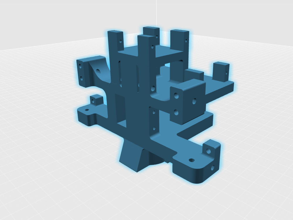
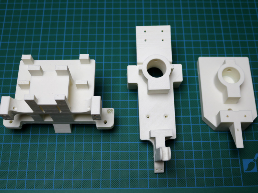
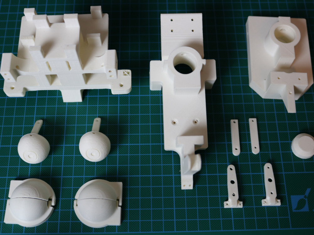
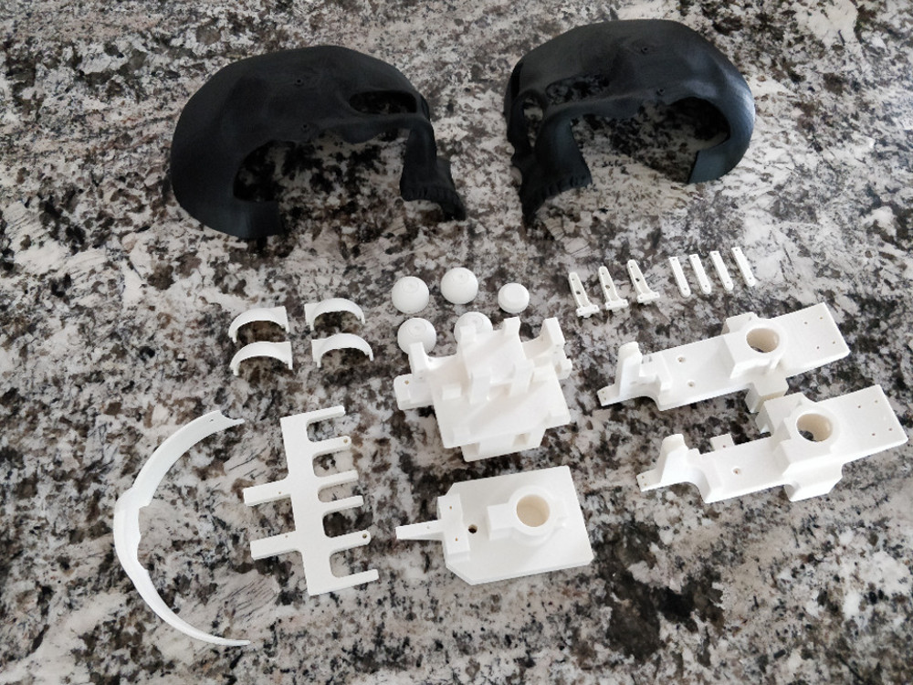
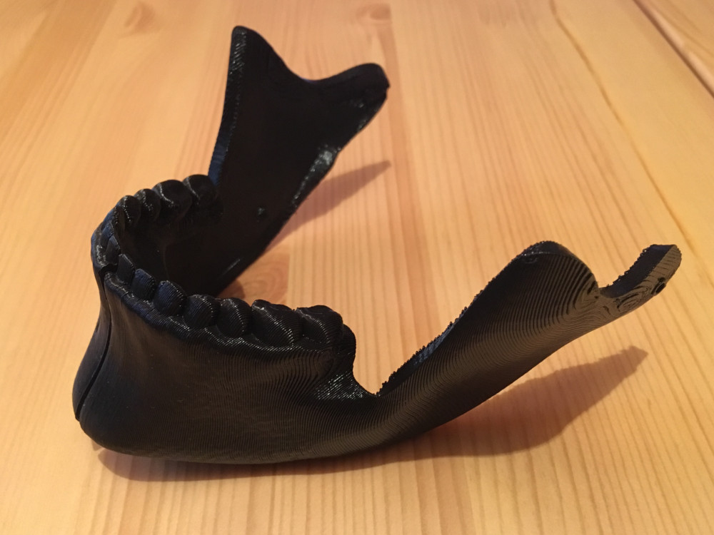
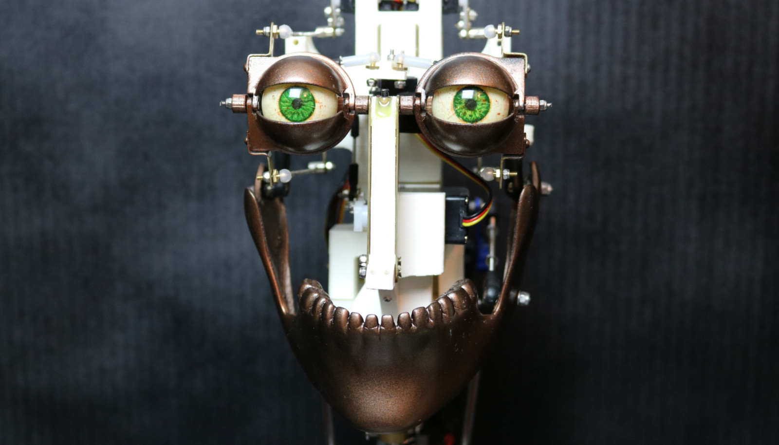
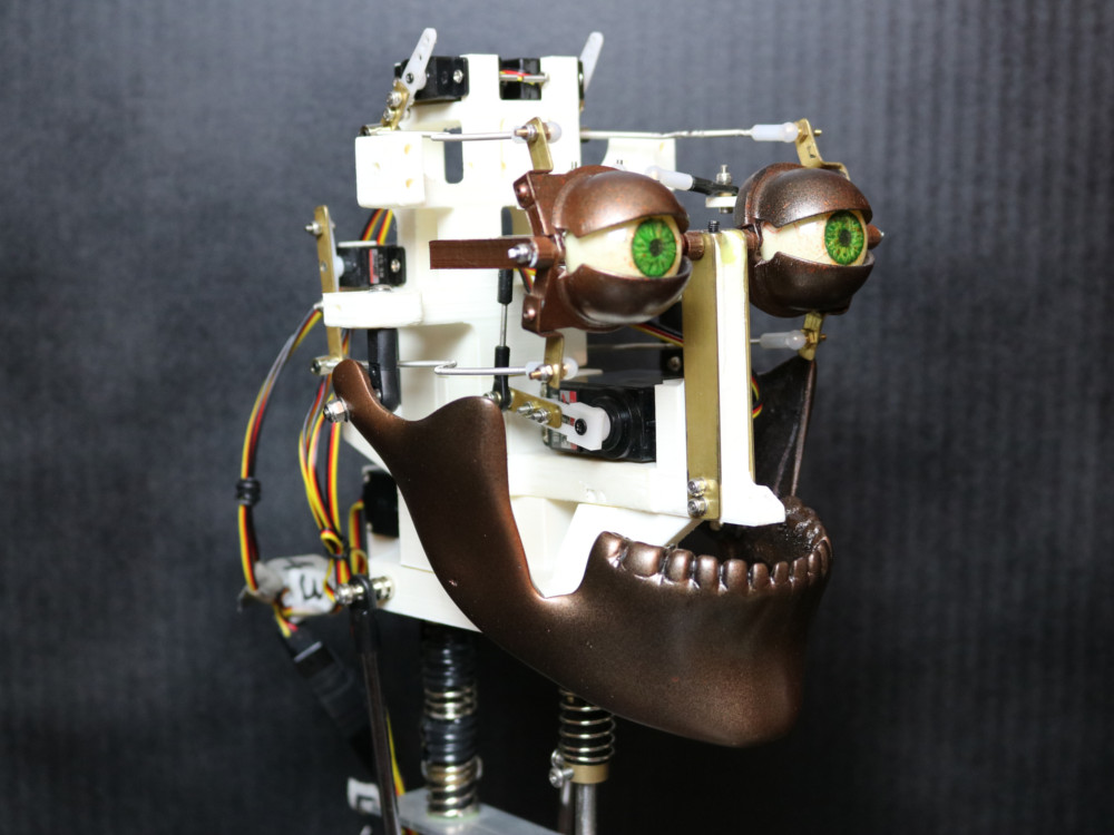
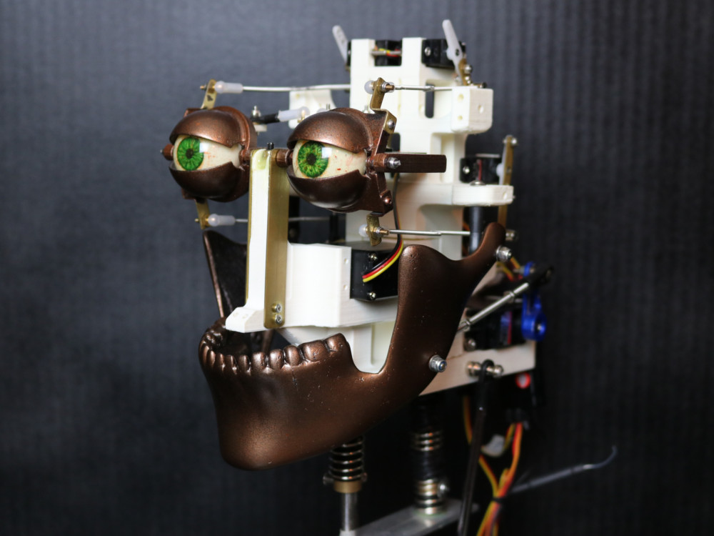
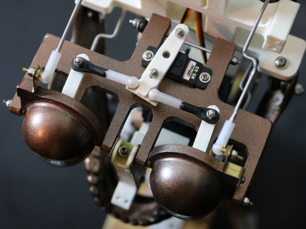
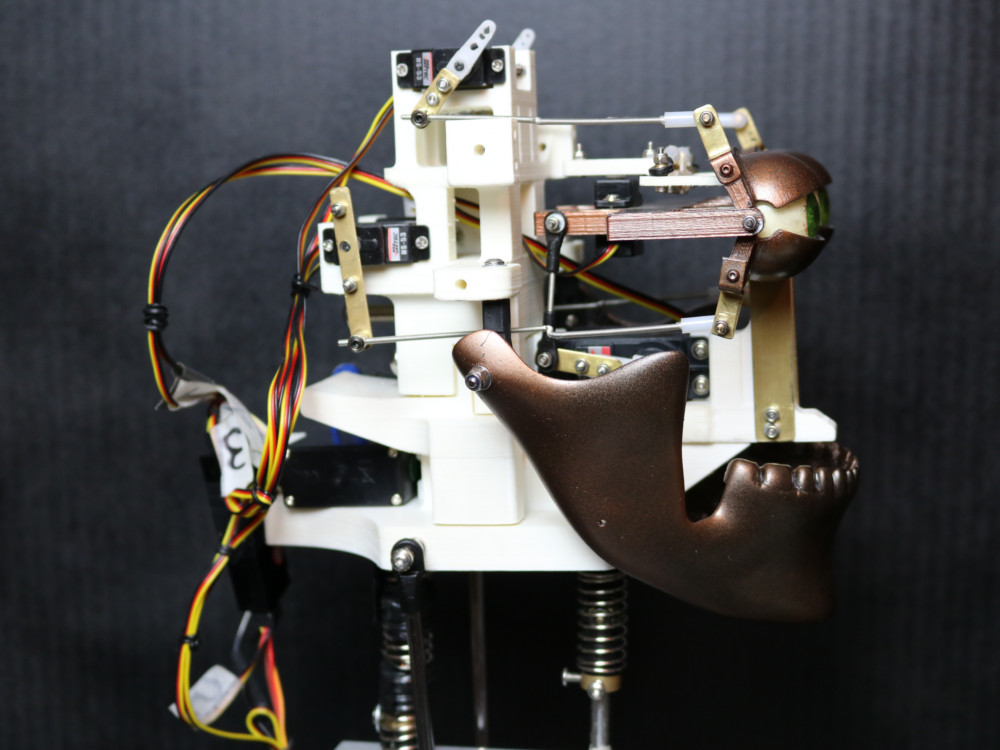
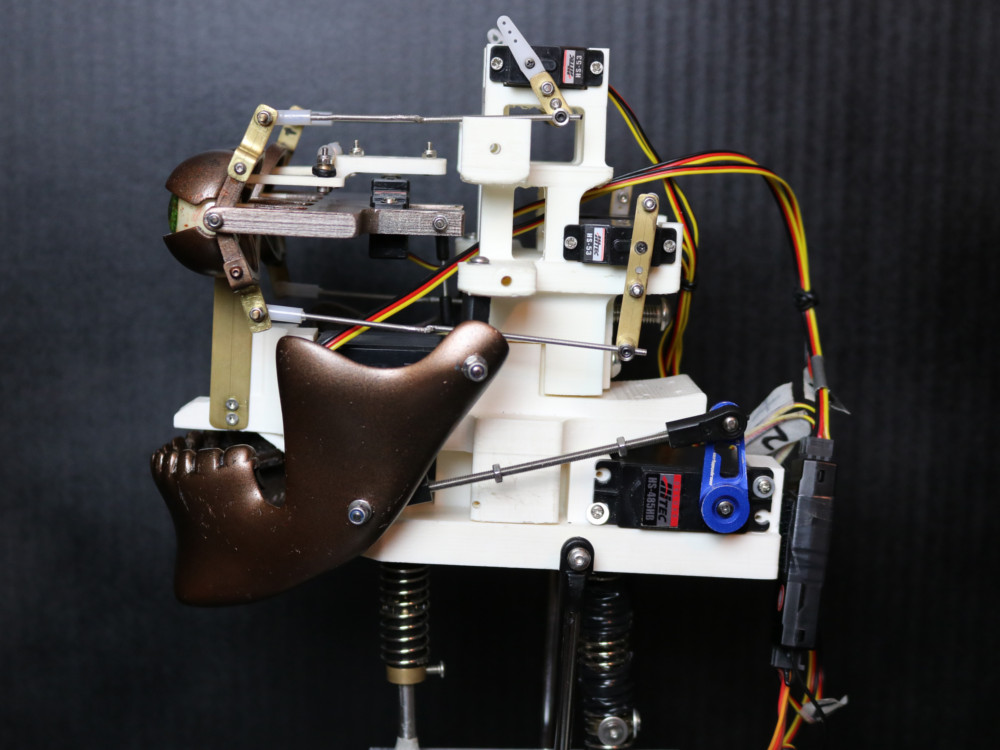
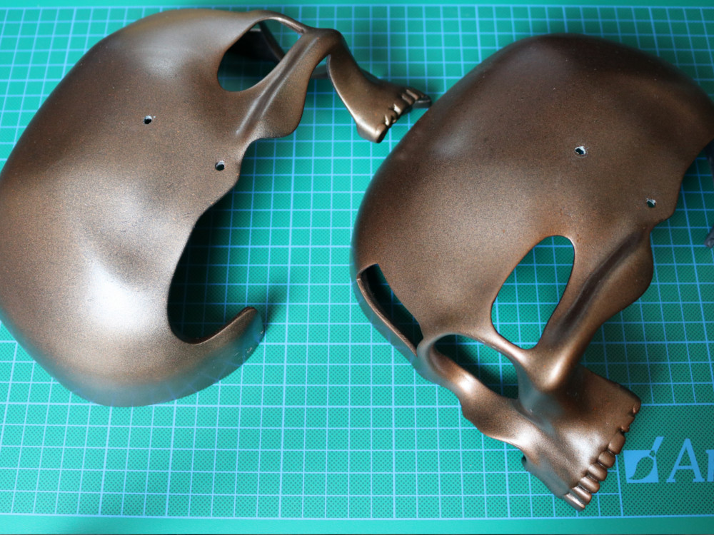
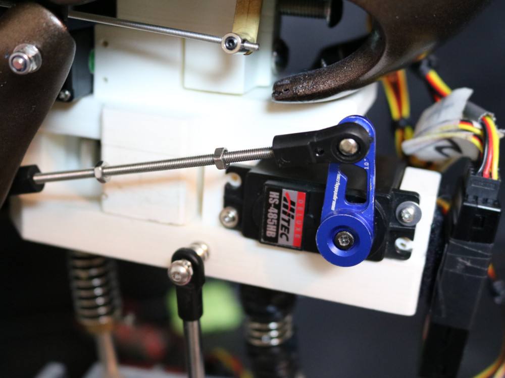
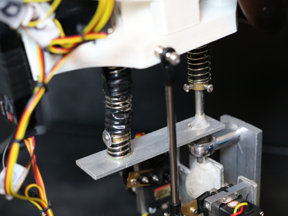
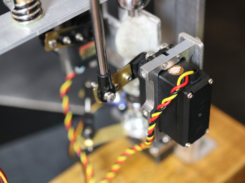
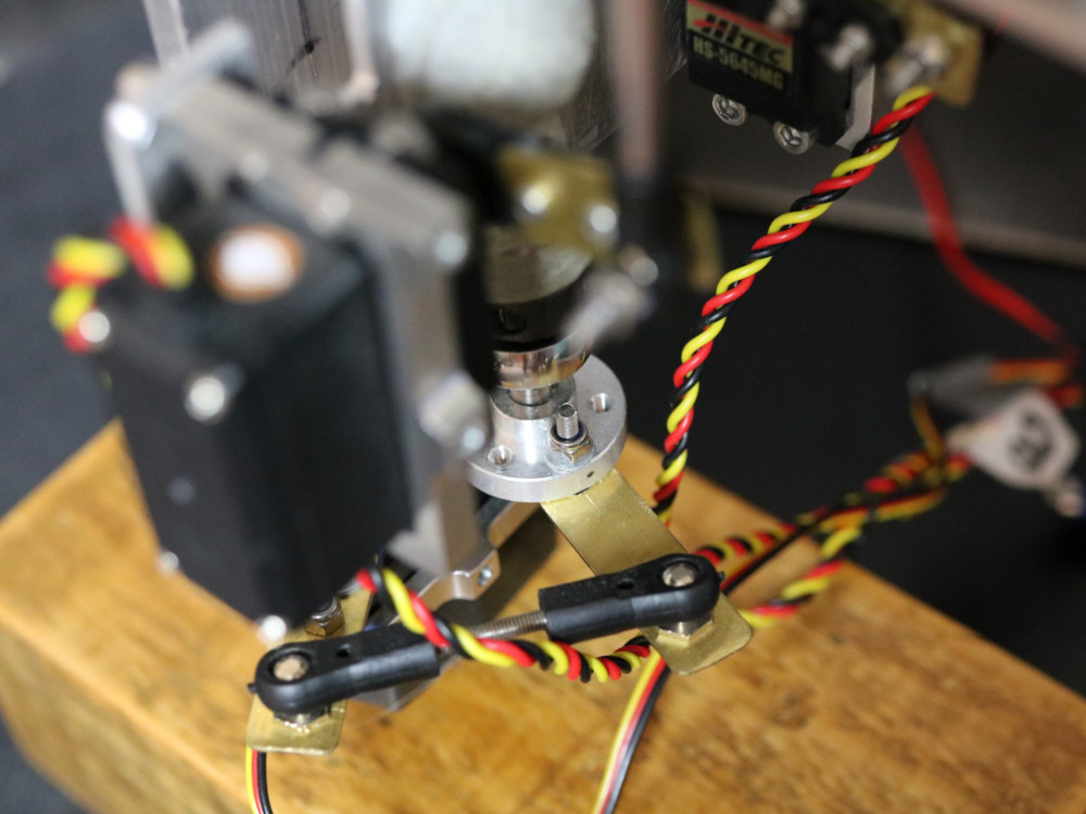
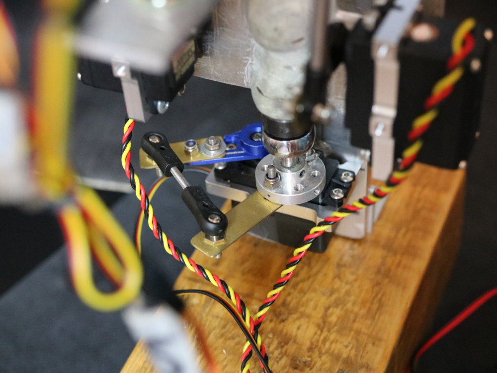
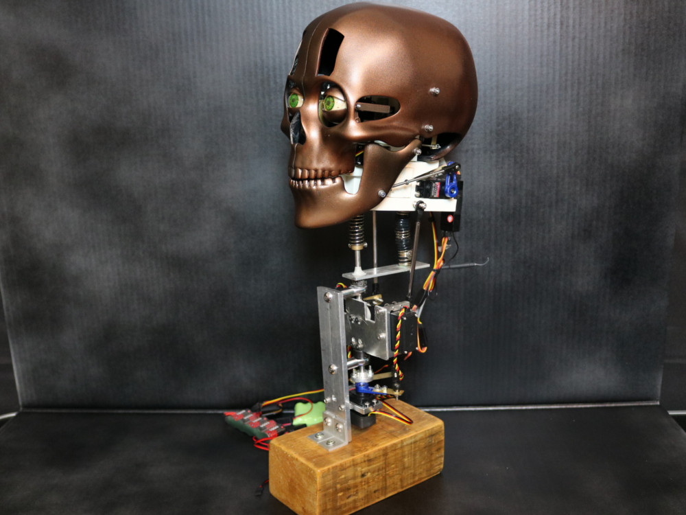
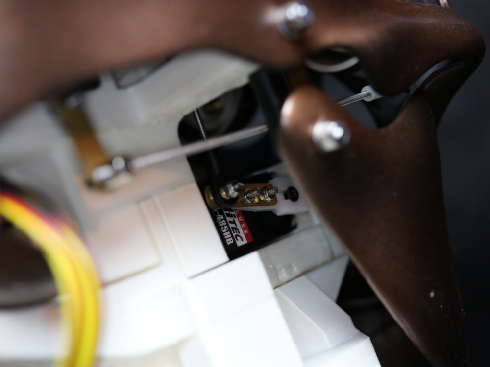
Using Autodesk Fusion 360, I modelled a mechanism that positioned the various motors relative to the moving parts, as well as supporting the outer skull. I also modelled the ball links, pulleys, screws, pushrods, servos and nearly all off-the-shelf parts I would require when building the head; this helped me visualize how it would all come together when printed. The tools in Fusion 360 allowed me to design, build and simulate the entire animatronic character from scratch in a 3D environment without having to fabricate prototypes out of metal or wood. The skull was modelled separately in Blender - See 3D Modelling In Blender.

animatronic animatronic animatronic animatronic animatronic animatronic animatronic animatronic
project

3D printed parts

All the parts were 3D Printed in Standard ABS - 100μm & 300μm using a Original Prusa i3 MK3 3D printer. The full mechanism requires 5 x Hitec HS-53 mini servos, 3 x Hitec HS-485HB and 2 x HS-5645MG servo motors. There are a few off-the-shelf parts such as M2 & M3 Ball Links, Pushrods and socket screws. The mechanism was modelled in seperate modules to allow for design updates without having to reprint everything. The parts mount to a 20mm aluminum shaft located in the centre that can be fitted to any alternative neck mechanism.

animatronic animatronic animatronic animatronic animatronic animatronic animatronic animatronic
project

Making eyeballs

The 3D printed eyeballs were sanded with 600-2500 wet & dry paper, hand painted with thinned acrylics and had single strands of red yarn applied with thinned Mod Podge to simulate the veins. I prepared a mould and cast the eyes in a clear cold cure acrylic resin, once cured the eyes were polished to give a glossy shine and improve the realism. Heat cure acrylic would have worked better to reduce the amount of air bubbles, these are the first eyeballs I have made, so I can improve on the next attempt. A 2mm brass tube fits in the centre which acts as the left/right rotation axis.

animatronic animatronic animatronic animatronic animatronic animatronic animatronic animatronic
project

Assembly

This animatronic head is the second I have designed in Fusion 360, the first attempt (See - Animatronic Design MK1) when printed just didnt give the right movement; so to make things simpler I used the so-called "E-Bar" method to move the eyes, which has one servo controlling the left and right rotation and another servo moving the eyes up and down. The jaw is controlled by one servo mounted at the back of the skull. The skull sections were sanded, primed and sprayed with a coat of black gloss & copper paint to make the robot look old and vintage.

animatronic animatronic animatronic animatronic animatronic animatronic animatronic animatronic
project

Neck mechanism

The lower portion of the Spud Block mounts onto a 12mm diameter Universal Joint (U-Joint), this is attached to a M6 steel rod that is then mounted to a servo at the bottom which controls the heads rotation. Two further servos move the push rods that are mounted on the sides of the Spud Block, controlling the left and right tilt. Some parts were constructed from aluminum and steel as the weight of the head would have been too much for standard ABS 3D prints; but this did allow me to put more load on the bottom servo and achieve greater control when puppeteering the head.

animatronic animatronic animatronic animatronic animatronic animatronic animatronic animatronic
project

Final outcome

And here is the final character ready for puppeteering. All in all this took me around eight months to make, from initial design to what you see here. This animatronic is a prototype and there is room for improvement. However, the mechanisms do move and operate as intended and I'm pretty satisfied with this as my first attempt. Two Hitec Transmitter radios are used to control the character; one for the eyes & jaw and the other controls the head/neck rotation (thanks to my wife who learned how to use an rc radio for this project). I only plan to make more and learn as much as I can along the way. Thank you for taking the time, you can watch a video below of the Animatronic Robot Head in action.

animatronic animatronic animatronic animatronic animatronic animatronic animatronic animatronic
  • Created by: K Meadows
  • Completed on: 22nd September 2018
  • Software: Fusion 360/Blender
  • Purpose: 3D Printed Animatronic
Share:

Project completion:

I'd very much like to work with other designers out there to collaborate on further projects.

Please take a moment to share my work and do get in touch - Get In Touch.

Other Projects: